How to Setup SIM900A GSM Module with Arduino Uno and NodeMCU
I used SIM900A Mini V3 GSM Module with my recent research project and when i compare it with other low cost GSM modules it seems to work really well, even in low signal situations. Here i’m going to discuss the problems that I faced and how I have solved them.
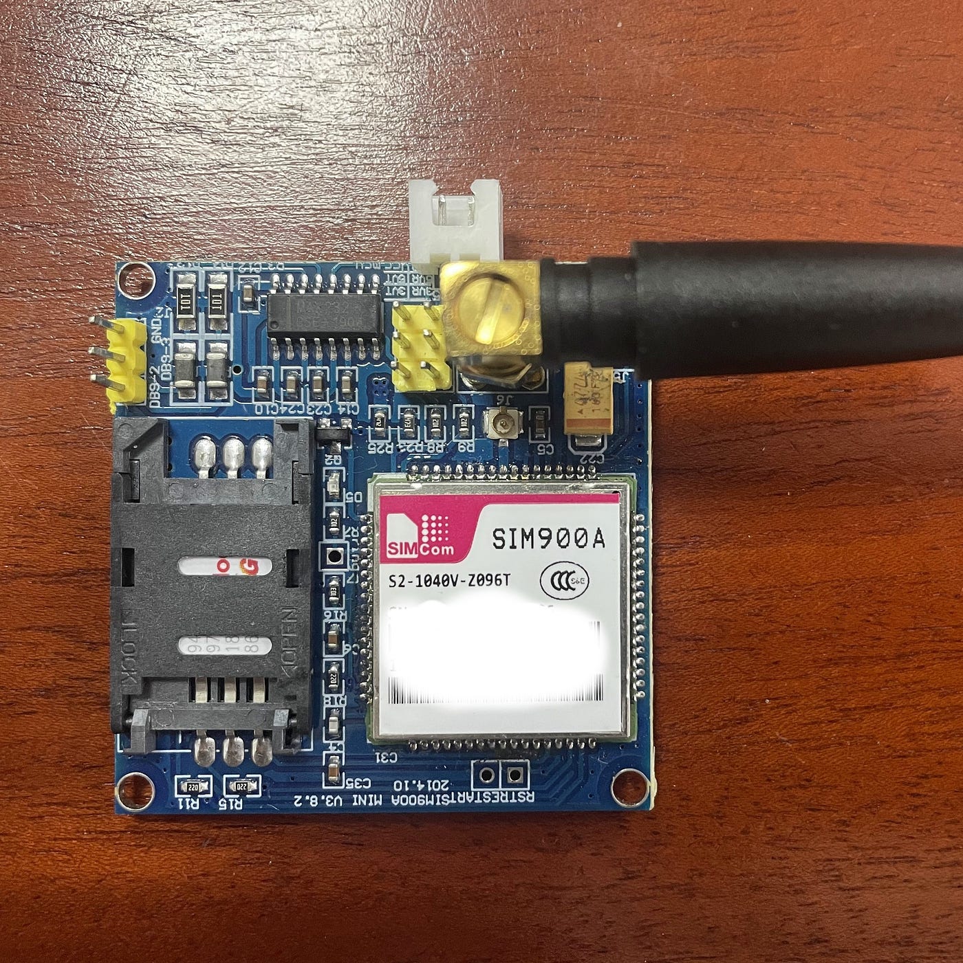
SIM900A GSM Module:
In SIM900A Mini GSM Module first important thing that i noticed is, there is no voltage regulator, So we need to be very carefully when applying the voltage; Because voltage greater than 5 V can damage this module easily. It’s better to use a 5V adapter when you are using this module. If you don’t have a power supply use can make a one using adjustable voltage regulator. I recommend you to use an external power supply for the GSM Module.
SIM900A GSM Module Pin Configuration:

The white connector is the place, where we should connect our external 5V regulated power. This module has 9 male headers but three male headers on the left side of the image are not connected.
- Pin 1: VCC
- Pin 2: Ground ( which will be connected to NodeMCU/UNO ground)
- Pin 3: 5 V RXD
- Pin 4: 5 V TXD
- Pin 5: 3.3 V TXD
- Pin 6 : 3.3 V RXD
NodeMCU Module based on the 3.3 V controller board so, we have to use 3.3 V TXD and RXD pins of the GSM module. In UNO we have to use 5V TXD and RXD pins of the GSM Module.
NodeMCU with SIM900A Diagram:

UNO with SIM900A Diagram:


Programming Code:
#include <SoftwareSerial.h>//Create software serial object to communicate with SIM900
//mySerial(7,8) for UNo, mySerial(D5,D6) in NodeMCUSoftwareSerial mySerial(7,8);void setup()
{
  //Begin serial communication with Arduino UNO/NodeMCU and Arduino IDE (Serial Monitor)
  Serial.begin(9600);

  //Begin serial communication with Arduino and SIM900
  mySerial.begin(115200);Serial.println("Initializing...");
  delay(1000);mySerial.println("AT"); //Once the handshake test is successful, it will back to OK
  updateSerial();
  mySerial.println("AT+CSQ"); //Signal quality test, value range is 0-31 , 31 is the best
  updateSerial();
  mySerial.println("AT+CCID"); //Read SIM information to confirm whether the SIM is plugged
  updateSerial();
  mySerial.println("AT+CREG?"); //Check whether it has registered in the network
  updateSerial();
}void loop(){
  updateSerial();
}void updateSerial()
{
  delay(500);
  while (Serial.available())
  {
    mySerial.write(Serial.read());//Forward what Serial received to Software Serial Port
  }
  while(mySerial.available())
  {
    Serial.write(mySerial.read());//Forward what Software Serial received to Serial Por6+t
  }
}
We have used usb TTL converter to power up SIM900A Module. After uploading this code you can use AT commands to communicate with GSM module. Here we have used 115200 baud rate.
